Filteration & Separator Skid
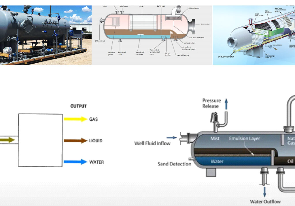
The system is designed to separate a multiphase wellstream—containing oil, water, gas, and sand—into its four individual components using physical separation methods (gravity, centrifugal force, and coalescing).
1. Stage 1: Inlet & Primary Separation (Gas & Free Liquids)
⦁ Purpose: Initial separation of gas and bulk liquids.
⦁ Process:
⦁ Well fluids enter the skid through an inlet diverter or cyclonic inlet, which reduces flow velocity to allow initial separation.
⦁ Gas rises due to low density and exits through a gas outlet for further treatment (e.g., flare, compression, or sales).
⦁ A mist extractor removes entrained liquid droplets from the gas stream.
⦁ Gas is sent to flare, fuel gas, or compression.
⦁ Liquids (oil, water, and sand) settle and flow into the next stage.
2. Stage 2: Sand & Solids Removal
⦁ Purpose: Remove abrasive solids (sand, silt, scale) to protect downstream equipment.
⦁ Process:
⦁ Liquids pass through a sand trap or desander (hydrocyclone or gravity-based).
⦁ Centrifugal force causes heavier sand/solids to spiral downward and settle at the bottom.
⦁ Sand & solids settle and are discharged via a sludge outlet (manual or automated).
⦁ The remaining liquid (oil & water) moves to the next stage.
3. Stage 3: Oil-Water Separation (Coalescing or Gravity-Based)
⦁ Purpose: Separate oil from water.
⦁ Process:
⦁ The liquid enters a coalescer or gravity separator or FWKO (Free Water Knockout). (e.g., API separator, CPI plate pack).
Gravity separation occurs: Oil (lighter) floats on top, water (heavier) settles at the bottom.
A coalescer pack may accelerate the oil droplet separation.
Level controllers regulate oil and water interface levels.
Oil is skimmed and flows out through the oil outlet.
Water exits from the bottom to water polishing stage.
4. Stage 4: Polishing (Water Treatment)
⦁ Purpose: Further clean water to meet disposal/reuse standards.
⦁ Process:
⦁ Water passes through a filter (media, cartridge, or membrane) or flotation unit (DAF – Dissolved Air Flotation), hydrocyclones, Induced Gas Flotation (IGF), or a Compact Flotation Unit (CFU).
⦁ Fine oil droplets are coalesced and floated to the top or spun out.
⦁ Remaining fine solids are removed.
⦁ Treated water is discharged or reinjected.
Key Components of the Skid:
⦁ Vessels: Separators, coalescers, sand traps.
⦁ Pumps & Controls: Transfer pumps, level sensors, automated valves.
⦁ Piping & Valves: Flow control between stages.
⦁ Instrumentation: Pressure gauges, temperature sensors, flow meters.
⦁ Safety Systems: Pressure relief valves, flame arrestors (if gas is present).
⦁ Level transmitters (oil/water interface)
⦁ Pressure transmitters
⦁ Temperature sensors
⦁ Automated valves and PLC control
Design & Engineering Standards
Standard
API 12J / API 421
API 650 / API 620
ASME Section VIII Div. 1 or 2
ANSI / ASME B31.3
ISO 10438 / API 614
ISO 13503 / API RP 13C
IEC 61508 / 61511
DNV-ST-F101 / DNVGL-OS-E201
Description
Design of oil-water separators
Design of large atmospheric storage tanks (if applicable)
Design and construction of pressure vessels
Process piping code
For lubrication systems and auxiliary equipment (relevant if included)
Sand handling and separation (desander specifications)
Functional safety for instrumentation and control systems
Offshore structural design standards
Material & Fabrication Standards
Standard
ASTM / ASME Standards
NACE MR0175 / ISO 15156
ISO 15138
ISO 3834 / EN 1090
PED 2014/68/EU
Description
Material grades for carbon steel, stainless steel, duplex, etc.
Material resistance to H₂S and sour gas environments
Ventilation, fire, and gas detection for offshore applications
Welding quality requirements
Pressure Equipment Directive (for EU projects)
Offshore & Marine Certifications
Certificate / Regulation
ABS / DNV / BV / Lloyd’s Register (LR)
ATEX / IECEx Certification
API Q1 / ISO 9001
EN 10204 (3.1 or 3.2)
CE Marking (if for EU)
NORSOK Standards (for North Sea)
UKCA (for UK market)
IMO MODU Code
Description
Classification society approval for offshore equipment
For hazardous area equipment (zones 1 & 2)
Quality management system certification
Material test certificates
Compliance with EU directives (especially PED)
Norwegian offshore equipment standards
Similar to CE, for UK post-Brexit compliance
Mobile Offshore Drilling Units safety standards (if applicable)
Testing & Inspection Requirements
⦁ Hydrostatic Testing – As per ASME/ISO
⦁ NDT (RT, UT, MT, PT) – As per ISO 9712 or ASNT standards
⦁ Factory Acceptance Test (FAT)
⦁ Site Acceptance Test (SAT)
⦁ Performance Testing (Oil-in-Water, Sand Removal Efficiency)
⦁ Explosion-proof Certification – For electrical panels and instrumentation
Documentation Package (Typical)
⦁ General Arrangement & P&ID
⦁ Data Sheets & Instrument Lists
⦁ Material Certificates (MTCs)
⦁ Welding Procedures & Welder Qualifications (WPS/PQR/WQT)
⦁ Coating & Painting Reports (ISO 12944)
⦁ Inspection & Test Plan (ITP)
⦁ FAT & SAT Reports
⦁ Operations & Maintenance Manual
⦁ Electrical Classification Drawing (for Ex zones)